VCQO
The VCQO is the heart of the Z-5 Console. There are a total of 7 VCQO circuits within the console, 3 of which are used to create the most basic abstract patterns. The other 4 are used for X, Y, Z Rotation and Orbit.
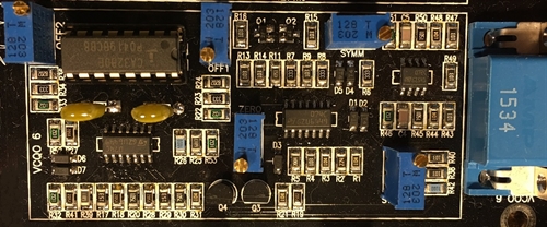
The image above represents a v4 circuit board. The v2 circuit board had the potentiometers in a single line. All 7 of the VCQO circuits function the same, the only difference is the frequency response, this will be discussed later. Here is the pot assignment and DB-15HD pin assignment:
DB-15HD v2
1. Rate
2. FM
3. Sine Hold
4. Sine Hold
5. Sine Out
6. Square Out (Sin)
7. LED
8. Square Out (Cos)
9. Cosine Out
10. External Start Point
11. Cosine Hold
12. Cosine Hold
1. Rate
2. FM
3. Sine Hold
4. Sine Hold
5. Sine Out
6. Square Out (Sin)
7. LED
8. Square Out (Cos)
9. Cosine Out
10. External Start Point
11. Cosine Hold
12. Cosine Hold
DB-15HD v4
1. Sine Hold
2. LED
3. Square Out (Cos)
4. FM
5. Rate
6. Square Out (Sin)
7. +15V
8. -15V
9. DC Common
10. Sine Out
11. Sine Hold
12. Cosine Hold
13. Cosine Out
14. Cosine Hold
15. External Start Point
1. Sine Hold
2. LED
3. Square Out (Cos)
4. FM
5. Rate
6. Square Out (Sin)
7. +15V
8. -15V
9. DC Common
10. Sine Out
11. Sine Hold
12. Cosine Hold
13. Cosine Out
14. Cosine Hold
15. External Start Point
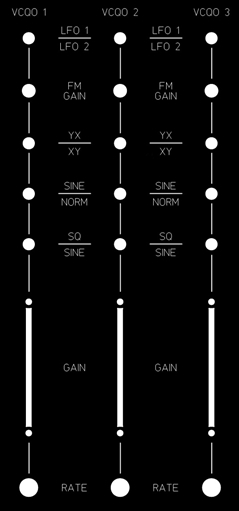
Pot Assignment and Function
- OFF 1 & 2 - These two 'Offset' trimmer pots set the center point for the output sine waves. Adjusting these pots requires an oscilloscope in X/Y mode.
- SYMM - This 'Symmetry' trimmer adjusts the frequency differential of the oscillator. For example, if you apply -15V to the 'Rate' pin on the DB-15HD connector, the output frequency ~650Hz, when you apply +15V to the Rate connector the output frequency should be ~650Hz, rotating in the opposite direction. If not, the Symm pot may be adjusted to match the speed at both ends.
- Zero - The Zero trimmer allows you to adjust the center dead spot of the potentiometers travel where the oscillator will come to a stop.
- Start - The Start trimmer sets up a bias on the oscillator when switched off. A start point isn't used on the three main VCQO oscillators and is only used on the X, Y, Z and Orbit oscillators.
Capacitor Value vs Frequency
+/-12V Supply:
470pF - 5KHz
4700pF - 518Hz
47,000pF - 52Hz
330,000pF - 7.5Hz
470pF - 5KHz
4700pF - 518Hz
47,000pF - 52Hz
330,000pF - 7.5Hz
+/-15V Supply:
470pF - 6KHz
4700pF - 612Hz
47,000pF - 61Hz
330,000pF - 8.4Hz
470pF - 6KHz
4700pF - 612Hz
47,000pF - 61Hz
330,000pF - 8.4Hz
Modifications
Rate Potentiometer - The rate potentiometer for the VCQO is a Bourns multi-turn, precision wire-wound device. It has a total of 10 turns and offers very fine control over the output frequency. The default wiring of a Z-5 puts +15V on one side of the potentiometer and -15V on the other. The wiper is fed directly to the 'Rate' input pin on the VCQO. When the 10-turn potentiometer is in the center of its travel, the VCQO stops, turning the pot clockwise a small amount will cause the oscillator to turn in one direction, turning the potentiometer counter-clockwise a bit will cause the oscillator to turn in the other direction.
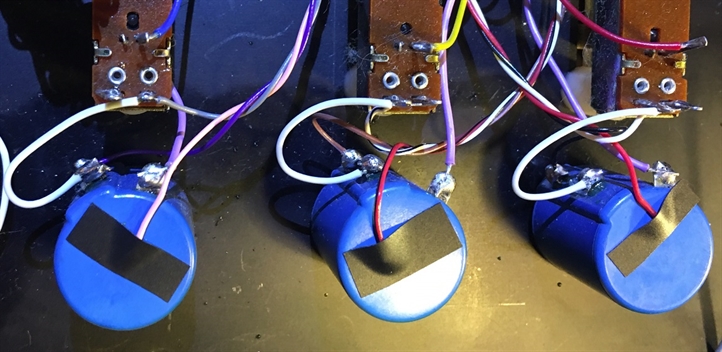
I decided to change how the potentiometer is wired to see if I could improve frequency control. By disconnecting the +15V wire (be sure to secure this loose wire so that it doesn't short to another component) from the number 2 pin on the potentiometer and replacing it with a wire to ground, you effectively double granularity.
The downside here is that you lose the ability to reverse the direction of the oscillator with the potentiometer. The good news is that this can still be accomplished via the YX/XY switch.
Overall, this is a very simple modification and is quite effective. In the image below you will see that the +15V (red/pink) wire is disconnected and secured to the bottom of the potentiometer. A small white wire is connected from the potentiometer to the ground connection on the slide potentiometer above it.
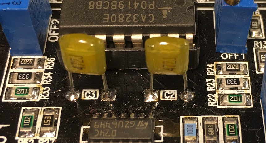
Timing Capacitors - Each VCQO has a pair of timing capacitors labelled C2 and C3. Unlike other capacitors in the circuit, these are 'Pin Thru Hole' mounted devices, primarily for the ease of replacing them. They must be in matched pairs and I recommend either polyester or polystyrene style capacitors. If you wish to increase the highest output frequency of the VCQO, simply remove the existing caps and replace them for another set. I have found that retuning isn't necessary. Increasing the capacitor value will decrease the top frequency of the VCQO while decreasing the capacitor value will increase the top frequency.
This modification I would rate as being easy, simply remove the two existing caps and replace with a different value. I currently use the following capacitor values in my Z-5 console:
VCQO 1 thru 3 - 4700pF
VCQO 4 (X Rotation) - 10,000pF
VCQO 5 (Y Rotation) - 10,000pF
VCQO 6 (Z Rotation) - 10,000pF
VCQO 7 (Orbit) - 47,000pF
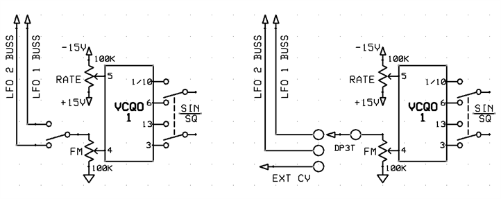
External CV - I was recently asked about the ability to control a VCQO from a signal external to the Z-5. The signal could be in the form of audio or a steady DC signal such as a CV or Control Voltage. So I've completed a bit of testing in this area and have determined that using audio as a source to modulate a VCQO leads to some rather undesireable results. I continued to experiement by filter out all higher frequencies of the audio signal and making the signal single ended. Again, I wasn't pleased with the results at all.
After some further testing I came to a realization, the FM modulation of the VCQO via an LFO works so well is due to the very repeatable nature of the LFO signal. So with this information I suspect that controlling a VCQO via an external CV will likely work very well whereas using an audio source will not.
Each VCQO has two inputs for frequency control, one labelled 'Rate' and the other labelled 'FM'. I believe that the best way to implement external CV control would be thru the FM port. The FM port is tied to a 50K potentiometer to control signal gain, and a SPDT switch to link either LFO 1 or LFO 2. If the SPDT switch were to be replaced with a DP3T switch, this would allow a user to flip between either of the two LFO's as well as an external CV.
Let's first take a look at signal specs, the VCQO FM input pin has 220K of input impedance and can accept a bi-polar signal of between -15V and +15V. The Rate and FM pins are summed together so any CV signal would be added to a current voltage level provided by the Rate potentiometer.
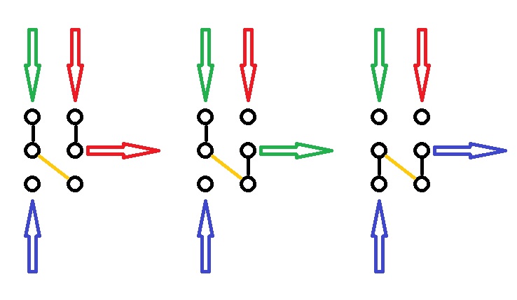
I would rate this modification as moderate due to the need to wire up a DP3T switch, which can be a bit tricky. It is very important that the Z-5 and the external CV share a common ground. The image at the bottom represents how the signal would flow thru a DP3T switch. The yellow line represents a wire that would need to be soldered to two terminals of the switch. The example on the left shows the switch lever in the down position, allowing the red signal to flow thru the switch. The middle example shows the switch lever in the center position, allowing the green signal to flow thru. Lastly, the example on the right shows the switch lever in the up position, allowing the blue signal to flow thru.
After some further testing I came to a realization, the FM modulation of the VCQO via an LFO works so well is due to the very repeatable nature of the LFO signal. So with this information I suspect that controlling a VCQO via an external CV will likely work very well whereas using an audio source will not.
Each VCQO has two inputs for frequency control, one labelled 'Rate' and the other labelled 'FM'. I believe that the best way to implement external CV control would be thru the FM port. The FM port is tied to a 50K potentiometer to control signal gain, and a SPDT switch to link either LFO 1 or LFO 2. If the SPDT switch were to be replaced with a DP3T switch, this would allow a user to flip between either of the two LFO's as well as an external CV.
Let's first take a look at signal specs, the VCQO FM input pin has 220K of input impedance and can accept a bi-polar signal of between -15V and +15V. The Rate and FM pins are summed together so any CV signal would be added to a current voltage level provided by the Rate potentiometer.
I would rate this modification as moderate due to the need to wire up a DP3T switch, which can be a bit tricky. It is very important that the Z-5 and the external CV share a common ground. The image at the bottom represents how the signal would flow thru a DP3T switch. The yellow line represents a wire that would need to be soldered to two terminals of the switch. The example on the left shows the switch lever in the down position, allowing the red signal to flow thru the switch. The middle example shows the switch lever in the center position, allowing the green signal to flow thru. Lastly, the example on the right shows the switch lever in the up position, allowing the blue signal to flow thru.