Z-5c Color Modulator Support
The Z-5c Color Modulator was created specifically for the Z-5 Analog Console. With some minor modifications, it can be adapted to other analog consoles or it can also be used with standard laser show software. The Z-5c is designed to handle 3 color channels (Red, Green and Blue).
The Z-5c has five main sections on the front panel. The OSCx sections generate a waveform that can be routed to any or all of the RGB outputs. The CHOP section generates blank spaces in all three color outputs despite what the main OSCx oscillators are doing. The MAIN section is the final output of the circuit and allows adjusting image brightness as well as signal source select.
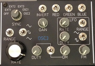
There are three main oscillators, identified as OSC1, OSC2 and OSC3. The lower left is the frequency control for the main oscillator. This oscillator has a 3 position RANGE switch and a 3 position function switch directly above the knob. Just to the right is the DUTY cycle potentiometer, center is 50/50 duty cycle. Just above DUTY is the GAIN potentiometer, setting the overall output signal gain of the oscillator. The output signal can also be inverted with the 2 position INVERT switch.
Above the LFO are three 2 position switches, these route the output signal of the oscillator to whichever color is selected. If you want a yellow image both RED and GREEN can be turned on. You can also have each OSCx oscillator applying it's signal to the same color.
The LFO generates a low frequency signal that may be used to modulate the main oscillator. The LFO has a 3 position RANGE switch, 2 position function switch and a potentiometer for adjusting DUTY cycle and frequency. Just below the LFO section are two potentiometers, FM will frequency modulate the main oscillator and DM will modulate the duty cycle of the main oscillator. The swtich between DUTY and DM is a 3 position switch, in the up position the DUTY potentiometer adjusts the duty cycle of the main oscillator. In the down position the DM potentiometer will adjust the duty cycle of the main oscillator. In the middle position, duty cycle of the main oscillator is fixed at 50/50.
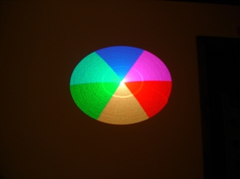
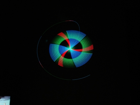
At the top left is 6 position rotary switch labelled SYNC. This allows the main oscillator to lock onto a base frequency or a harmonic of an external signal. In the off position the main oscillator runs free. The first three settings allows a sync to an external signal. When coupled with the Z-5 Analog Console, the three EXTx signals are the 3 main quadrature oscillators of the Z-5. The last two settings allow the oscillator to sync with one of the other OSCx oscillators on the Z-5c. For example, you can have OSC1 sync'd to an external signal (Z-5), OSC2 can then sync to OSC 1 and OSC3 can sync to OSC2, or any combination. The photo below may appear simple enough, it's an example of the sync settings described above.
Above the LFO are three 2 position switches, these route the output signal of the oscillator to whichever color is selected. If you want a yellow image both RED and GREEN can be turned on. You can also have each OSCx oscillator applying it's signal to the same color.
The LFO generates a low frequency signal that may be used to modulate the main oscillator. The LFO has a 3 position RANGE switch, 2 position function switch and a potentiometer for adjusting DUTY cycle and frequency. Just below the LFO section are two potentiometers, FM will frequency modulate the main oscillator and DM will modulate the duty cycle of the main oscillator. The swtich between DUTY and DM is a 3 position switch, in the up position the DUTY potentiometer adjusts the duty cycle of the main oscillator. In the down position the DM potentiometer will adjust the duty cycle of the main oscillator. In the middle position, duty cycle of the main oscillator is fixed at 50/50.
At the top left is 6 position rotary switch labelled SYNC. This allows the main oscillator to lock onto a base frequency or a harmonic of an external signal. In the off position the main oscillator runs free. The first three settings allows a sync to an external signal. When coupled with the Z-5 Analog Console, the three EXTx signals are the 3 main quadrature oscillators of the Z-5. The last two settings allow the oscillator to sync with one of the other OSCx oscillators on the Z-5c. For example, you can have OSC1 sync'd to an external signal (Z-5), OSC2 can then sync to OSC 1 and OSC3 can sync to OSC2, or any combination. The photo below may appear simple enough, it's an example of the sync settings described above.
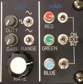
On the right side of the console you will find CHOP and MAIN. The CHOP section allows you to create a signal that will cut into the signal created in the three main OSCx sections. The CHOP signal is completely independant of the other oscillators. There are three potentiometers to adjust frequency, gain and duty of the chopping signal. The CHOP also has three frequency ranges and three different waveforms to select from.
The MAIN out section controls the signal source and final output gain of the Z-5c. Each color has a 3 position switch that allows you to turn on a particular color, link a color to an external signal (such as a DAC) or link the color to the Z-5c. The potentiometer adjusts the gain of the output signal.
The MAIN out section controls the signal source and final output gain of the Z-5c. Each color has a 3 position switch that allows you to turn on a particular color, link a color to an external signal (such as a DAC) or link the color to the Z-5c. The potentiometer adjusts the gain of the output signal.