X Y Z Rotation Matrix
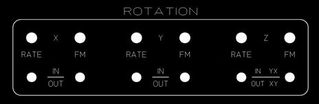
The X, Y and Z Rotation feature is a very unique function of the Z-5. Each rotator circuit requires a dedicated VCQO to handle its operation. The sine/cosine signal from the VCQO's are fed to the rotation matrix circuit, which features six AD534 analog multiplier IC's. Each rotator also has the ability to be frequency modulated via a hardwired signal fed from LFO 1.
When not in use, the IN/OUT switch is flipped to the down position. This locks the VCQO in a pre-defined state that sets up a bias on the rotation matrix circuit. The bias level is configured via the 'Start' trimmer potentiometer within the VCQO circuit.
By default, the Rate potentiometer is bi-polar. When this pot is centered, image rotation will stop, when turned clockwise the image will rotate in one direction, when turned counter-clockwise the image will rotate in the opposite direction.
Modifications
Rate Potentiometer - The standard potentiometer in the Z-5 for rotation is a single 270 degree pot. The problem is that you don't have a whole lot of granularity, so the slightest touch of the pot can yeild significant change in rotation frequency. To offset this, you can change the rate potentiometer with a multi-turn potentiometer, this will give much better control over the rotation frequency however, finding the center point where the rotation stops will be more difficult.
On my console, I decided to change all three rotation pots with Bourns multi-turn precision pots as well as making them single ended. This greatly increased fine control over frequency. The front panel wasn't designed to handle the larger potentiometer so you would need to increase the drill hole size to accomodate the larger shaft of the Bourns pot.
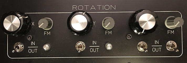
Changing the potentiometer from bi-polar to single ended (-15V and ground instead of -15V and +15V) will make finding the stop point of the VCQO very simple, just turn fully counter-clockwise. The downside is that you cannot reverse the direction of the rotation via the potentiometer. This is less of a problem on X and Y rotation as it's nearly impossible to determine in which direction the image is spinning. On Z roation is where the deficiency is a bit more apparent. You can still change Z rotation direction via the YX/XY switch. The nomenclature is not shown on the pic below since it was introduced after the first console was created.
On my console, I decided to change all three rotation pots with Bourns multi-turn precision pots as well as making them single ended. This greatly increased fine control over frequency. The front panel wasn't designed to handle the larger potentiometer so you would need to increase the drill hole size to accomodate the larger shaft of the Bourns pot.
Changing the potentiometer from bi-polar to single ended (-15V and ground instead of -15V and +15V) will make finding the stop point of the VCQO very simple, just turn fully counter-clockwise. The downside is that you cannot reverse the direction of the rotation via the potentiometer. This is less of a problem on X and Y rotation as it's nearly impossible to determine in which direction the image is spinning. On Z roation is where the deficiency is a bit more apparent. You can still change Z rotation direction via the YX/XY switch. The nomenclature is not shown on the pic below since it was introduced after the first console was created.
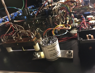
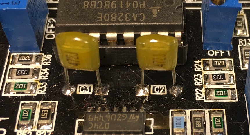
Timing Capacitors - After making the changes above, I decided to also increase the speed of the X, Y and Z oscillators. This allows for much more complex abstracts to be created. Changing the tuning capacitors is a very simple process. These capacitors are radial lead, pin thru hole, making them very easy to remove and replace.
It is important to change both C2 and C3 with as closely match capacitors as possible and it is recommended to use either polyester or polystyrene components. In my console, I currently use 10,000pF (103) capacitors for all three rotation oscillators.
On the main Z-5 circuit board, the rotation function is handled by the following VCQO's:
X Rotation - VCQO 4
Y Rotation - VCQO 5
Z Rotation - VCQO 6
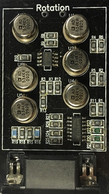
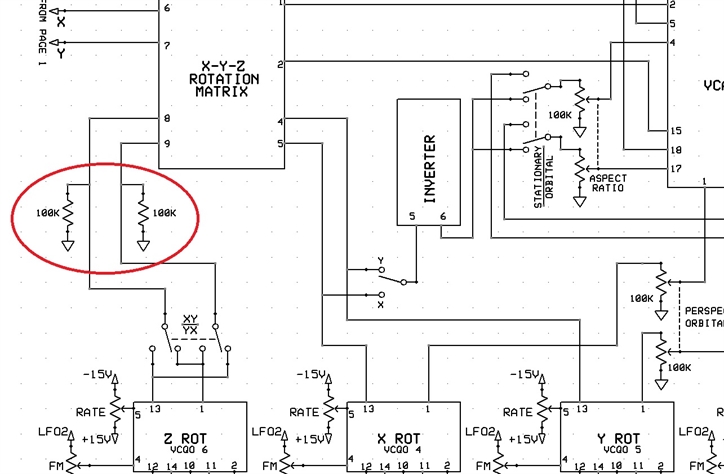
YX/XY Stability - The Z rotator has an XY to YX switch which swaps the sine/cosine signals to cause an immediate 90 degree turn of an image being displayed. The output of this switch feeds the non-inverting inputs of an op-amp. During the transition of the toggle switch these inputs float causing the scanners to quickly jump to a far corner of the scanning field. The only way to prevent this is to add two pull down 100K resistors. Instead of the beam jumping to a corner, the beam will jump to center during the transition.
The pic below shows where the pull down resistors need to be located.
The pic below shows where the pull down resistors need to be located.
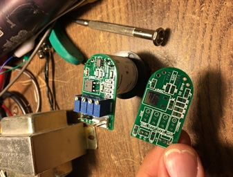
Manual Z Rotation - This feature allows you to set manually the rotation angle of a displayed image. By utilizing a sine-cosine potentiometer we can completely remove the VCQO from the rotator circuit. The pics below show the sine-cosine potentiometer mounted to the panel as well as the interface circuit to condition the signal for use by the rotation matrix circuit. The video below shows the effect of using the sine-cosine potentiometer.
Due to the complex nature of this upgrade, it is highly recommended that the Z-5 not be upgraded in the field.
Due to the complex nature of this upgrade, it is highly recommended that the Z-5 not be upgraded in the field.