
LaserScope Color Vector Visualizer
LaserScope is an iOS app designed for the iPhone or iPad. It requires a compatible external USB multi-channel audio device to work properly. Preferably, one that is designed around the ILDA standard with regard to ADAT recording and playback. I offer such a device called the Wave-USB; however, any multi-channel device should work if it's compatible with Apple's Core Audio.
LaserScope has numerous tools to be able to see line level audio vector images, similar to X/Y mode of an oscilloscope. What's unique is the addition of RGB.
The ideal USB audio device will support 8 channels in and 8 channel out with a minimum of 5 channels in and 0 channels out. By default, the app will set the sample rate to 48KHz.
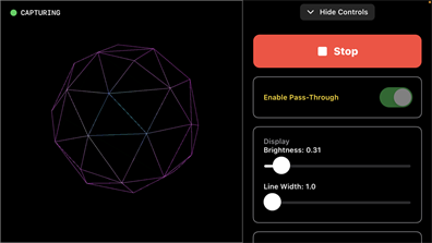
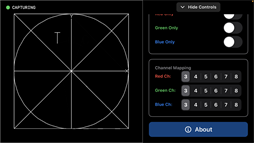
When the app first starts, the audio capture engine is idle. Before starting the capture, you can enable or disable pass-through. This cannot be changed while the capture is running. When enabled, all 8 channels of the input to the USB audio device are passed to the 8 channels out; channel 1 in goes to channel 1 out, channel 2 in goes to channel 2 out, etc. None of the settings on the LaserScope control panel affect the pass-through signal; all 8 channels, including XY and RGB, are unchanged. However, the iPhone's or iPad's volume control does affect all 8 channels simultaneously.
On the control panel, the rendered image brightness and drawn line width can be changed.
On the control panel, the rendered image brightness and drawn line width can be changed.
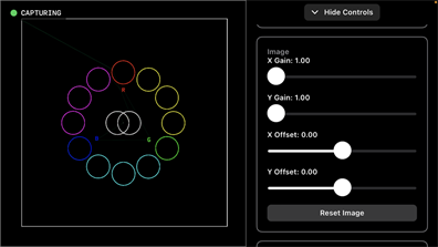
Moving down the control panel, you will find individual X/Y gain and offset sliders to take full advantage of the rendering window. These controls do not affect any signals that may be passing through the audio device.
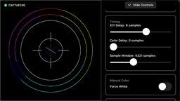
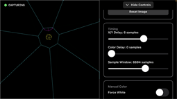
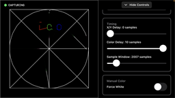
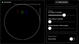
The images above show the next few tools on the control panel.
Timing, delay allows for the addition of a slight signal delay that can be added to either XY or RGB. This helps to ensure that the vector image and color properly line up.
Sample Window adjusts the timing for how much of a vector image is drawn over time. If you have a very complex image, this may need to be increased; a very fast image and this may need to be reduced.
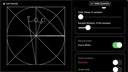
Manual Color, this forces white to a vector image regardless of the incoming RGB signals. This is beneficial for determining what the image is doing during the blanked parts or just diagnosing an incoming RGB signal issue.
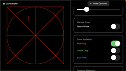
Color Isolation, this allows quick isolation of a single color. Only 1 toggle switch can be active at a time, and turning them off reverts to a full-color image.
Timing, delay allows for the addition of a slight signal delay that can be added to either XY or RGB. This helps to ensure that the vector image and color properly line up.
Sample Window adjusts the timing for how much of a vector image is drawn over time. If you have a very complex image, this may need to be increased; a very fast image and this may need to be reduced.
Manual Color, this forces white to a vector image regardless of the incoming RGB signals. This is beneficial for determining what the image is doing during the blanked parts or just diagnosing an incoming RGB signal issue.
Color Isolation, this allows quick isolation of a single color. Only 1 toggle switch can be active at a time, and turning them off reverts to a full-color image.

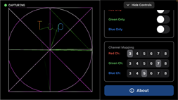
The last section, Color Mapping, allows a user to make changes to the source for the RGB colors. Standard ILDA channel assignments have Red on CH3, Green on CH4, Blue on CH5, Aux on CH6, Left Audio on CH7 and Right Audio on CH8. In the upper right image I have green assigned to CH7 so the color is being modulated by the incoming audio to the USB device.