
AudioLaze Support
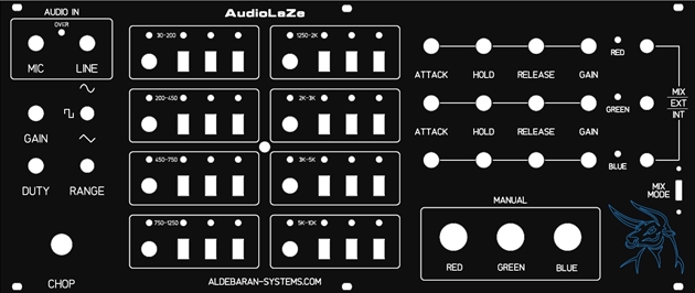
This page will go over the various functions of the AudioLaze. The AudioLaze was designed to handle RGB color modulation based on an audio source while a user can concentrate on building live X/Y abstracts during a laser show.
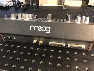
The rear of the AudioLaze. Standard 110VAC, 1Amp power connector. Two RCA audio in jacks, these are for Left/Right audio which are summed together within the AudioLaze.
ILDA IN and ILDA OUT. The AudioLaze is not capable of fully controlling a laser projector and requires that a DAC or analog console be attached to control X/Y, shutter and ILDA interlock. The AudioLaze is only capable of manipulating the RGB signals.
ILDA IN and ILDA OUT. The AudioLaze is not capable of fully controlling a laser projector and requires that a DAC or analog console be attached to control X/Y, shutter and ILDA interlock. The AudioLaze is only capable of manipulating the RGB signals.
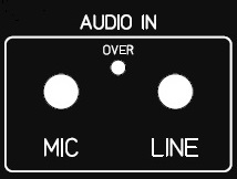
The Audio IN potentiometers control the volume of audio entering the AudioLaze. The built in microphone sensitivity is contolled by the potentiometer labelled MIC and the external audio via the RCA connectors on the rear of the Moog enclosure are controlled by the potentiometer labelled LINE.
Between the two potentiometers is an LED that indicates when the LINE IN signal level is exceeding the prime audio volume for the best possible quality of color output. This volume level is controlled externally. It is possible to have the LINE potentiometer fully counter-clockwise and have this LED lit due to an over-excessive audio signal. No harm can be done to the AudioLaze when this LED is lit, in fact, you might find that you prefer the color response when in this condition. However, for the absolute best possible dynamic color range and response from the AudioLaze, this LED will remain off.
Between the two potentiometers is an LED that indicates when the LINE IN signal level is exceeding the prime audio volume for the best possible quality of color output. This volume level is controlled externally. It is possible to have the LINE potentiometer fully counter-clockwise and have this LED lit due to an over-excessive audio signal. No harm can be done to the AudioLaze when this LED is lit, in fact, you might find that you prefer the color response when in this condition. However, for the absolute best possible dynamic color range and response from the AudioLaze, this LED will remain off.
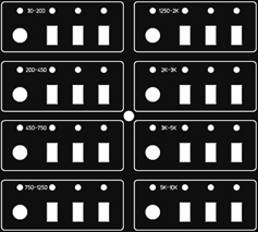
This section is the heart of the AudioLaze. Eight individual bandpass filters to separate the audio into specific frequency ranges. Each channel has a sensitivity control potentiometer with white LED feedback indicating when a specific frequency range has been detected. When the channel detects a freqency in range, an output signal is generated.
Next to the sensitivity potentiometer are 3 slide switches in each channel. These allow a user to specify what color (RGB) should be generated when a frequency is detected.
Next to the sensitivity potentiometer are 3 slide switches in each channel. These allow a user to specify what color (RGB) should be generated when a frequency is detected.
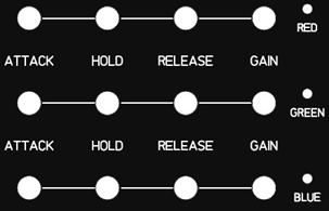
This section of the AudioLaze controls how the output color signals are generated when pulse is generated by the bandpass filter circuit. When a color pulse is generated, an LED indicating the color will illuminate.
Attack - This controls how quickly a color will turn on when a pulse is detected. When fully counter-clockwise, a pulse generated by the bandpass filter will cause the output of the color to turn on as quickly as possible. When turned clockwise, this will delay how long it takes for the color to reach full power.
Hold - Once a color has made it to full brightness, the Hold potentiometer will set how long the color remains at full power. Fully counter-clockwise will offer no hold time and the color signal will immediately begin to fall.
Release - This potentiometer will set how long it takes for the color signal to go from full brightness to zero brightness. Fully counter-clockwise will cause the color signal to go from full brightness to no brightness nearly immediately.
Gain - This potentiometer sets the overall brightness of the output signal. Fully clockwise will allow the color signal from the AudioLaze to travel from 0V to a full 5V output.
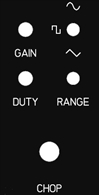
The Chopping circuit adds an additional layer of effects to the final output signal. Frequency of the Chopping signal is controlled by a 10-turn precision potentiometer and is divided into 3 frequency ranges from around 2Hz to 10KHz. The shape of the chopping signal can be sine, square or triangle and the duty cycle or shape of the selected signal can be set with the DUTY potentiometer.
The GAIN potentiometer sets intensity of the shopping signal. Fully counter-clockwise does not affect the AudioLaze output RGB signals at all./
The GAIN potentiometer sets intensity of the shopping signal. Fully counter-clockwise does not affect the AudioLaze output RGB signals at all./
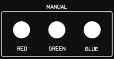
This section provides and easy way to trigger an output color via a push button. The Attack and Release potentiometer will affect how quickly the signal will rise and fall when a color button is pressed however, the Hold potentiometer will have no affect when using the manual color push buttons. Instead, hold the button in the down position will keep the color on until release, then the release time will depend on the Release potentiometer.
This is the final output stage of the AudioLaze. Here you can set which RGB signal is passed to the ILDA out and on to a connected laser projector. There are three switches with 3 positions and a slide switch.
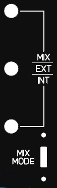
INT - In the INT switch position, any RGB signal generated by the AudioLaze is passed directly to the ILDA out.
EXT - In the EXT switch position, the AudioLaze is completely ignored and any signal from a host DAC connected to ILDA IN is passed to ILDA OUT.
MIX - In the MIX switch position, the internally generated RGB signal from the AudioLaze and the externally generated RGB signal from a DAC connected to the ILDA IN, are mixed together. However, this is a logical AND configuration. A color will display only if the AudioLaze AND the connected DAC are generating a color. Ultimately, this maintains the blanking signal from a connected DAC.
Mix Mode - This slide switch offers 2 possibilities when the above toggle switch is in the Mix position. In the up position, any signal generated by the AudioLaze will display on any color generated by a connected DAC. For example, if the host DAC is sending the signal to display a RED circle and a GREEN square, and the AudioLaze is only sending a BLUE color signal, both the RED circle and GREEN square will show up BLUE with no blanking lines being displayed.
When the MIX mode switch is in the down position, and again, you are displaying a RED circle and GREEN square from a connected DAC, the AudioLaze is sending a BLUE signal, no color will be projected from the laser projector. Only when the AudioLaze sends a RED signal will the RED circle display and only when the AudioLaze sends a GREEN square will the GREEN square display.
When the MIX mode switch is in the down position, and again, you are displaying a RED circle and GREEN square from a connected DAC, the AudioLaze is sending a BLUE signal, no color will be projected from the laser projector. Only when the AudioLaze sends a RED signal will the RED circle display and only when the AudioLaze sends a GREEN square will the GREEN square display.